Saturday, December 13, 2014

Raspberry Pi getting data from a S7-1200 PLC


UPDATE: If you want the raspberry pi to be the s7 server go here
UPDATE 2: If you want to see communication with S7-200 go here
UPDATE 3: Video walkthrough on setup go here

I recently borrowed a S7-1200 PLC from work to see if I could get data from it using a Raspberry Pi. In my search for something I found that Snap7 was the best option.
Steps to getting it work
  1. Download and compile snap7 (http://sourceforge.net/projects/snap7/files/1.2.1/snap7-full-1.2.1.tar.gz/download)
  2. Download and install python library to use snap7 (https://pypi.python.org/pypi/python-snap7)


#download and compile snap7 for rpi

wget http://sourceforge.net/projects/snap7/files/1.2.1/snap7-full-1.2.1.tar.gz/download 
tar -zxvf snap7-full-1.2.1.tar.gz
cd snap7-full-1.2.1/build/unix
sudo make –f arm_v6_linux.mk all

#copy compiled library to your lib directories
sudo cp ../bin/arm_v6-linux/libsnap7.so /usr/lib/libsnap7.so
sudo cp ../bin/arm_v6-linux/libsnap7.so /usr/local/lib/libsnap7.so

#install python pip if you don't have it:
sudo apt-get install python-pip
sudo pip install python-snap7

You will need to edit the lib_location on common.py in the /usr/local/lib/python2.7/dist-packages/snap7/ directory
Add a line in the __init__ part of the Snap7Library class:
lib_location='/usr/local/lib/libsnap7.so' 
example below:


class Snap7Library(object):
    """
    Snap7 loader and encapsulator. We make this a singleton to make
    sure the library is loaded only once.
    """
    _instance = None
    def __new__(cls, *args, **kwargs):
        if not cls._instance:
            cls._instance = object.__new__(cls)
            cls._instance.lib_location = None
            cls._instance.cdll = None
        return cls._instance

    def __init__(self, lib_location=None):
        lib_location='/usr/local/lib/libsnap7.so' # add this line here
        if self.cdll:
            return
        self.lib_location = lib_location or self.lib_location or find_library('snap7')
        if not self.lib_location:
            msg = "can't find snap7 library. If installed, try running ldconfig"
            raise Snap7Exception(msg)
        self.cdll = cdll.LoadLibrary(self.lib_location)

Now you can write your client code :-)
Here's an example on how to connect and read an output Q0.0:
from time import sleep
import snap7
from snap7.util import *
import struct

plc = snap7.client.Client()
plc.connect("192.168.12.73",0,1)

area = 0x82    # area for Q memory
start = 0      # location we are going to start the read
length = 1     # length in bytes of the read
bit = 0        # which bit in the Q memory byte we are reading

byte = plc.read_area(area,0,start,length)
print "Q0.0:",get_bool(mbyte,0,bit)
plc.disconnect()


I created a helper class on my github here to make the syntax easier for people who are used to DAServer and Ladder:
https://github.com/SimplyAutomationized/raspberrypi/raw/master/S7-1200pi/S71200.py
Example on how to use it:
import S71200
from time import sleep
import snap7
from snap7.util import *
import struct

plc = S71200.S71200("192.168.21.65")
plc.writeMem('QX0.0',True) # write Q0.0 to be true, which will only turn on the output if it isn't connected to any rung in your ladder code
print plc.getMem('MX0.1') # read memory bit M0.1
print plc.getMem('IX0.0') # read input bit I0.0
print plc.getMem("FREAL100") # read real from MD100
print plc.getMem("MW20") # read int word from MW20
print plc.getMem("MB24",254) # write to MB24 the value 254
plc.plc.disconnect()


Let me know if there are questions. Hope I can help :-)
Also let me know if you can help me clean up my S71200.py helper class. I know it looks messy.

Follow me to get updates on a Raspberry pi Sensor the DA or OPC server can get data using S7 protocol.
+Simply Automationized
Check out my other SCADA posts

Tuesday, August 26, 2014

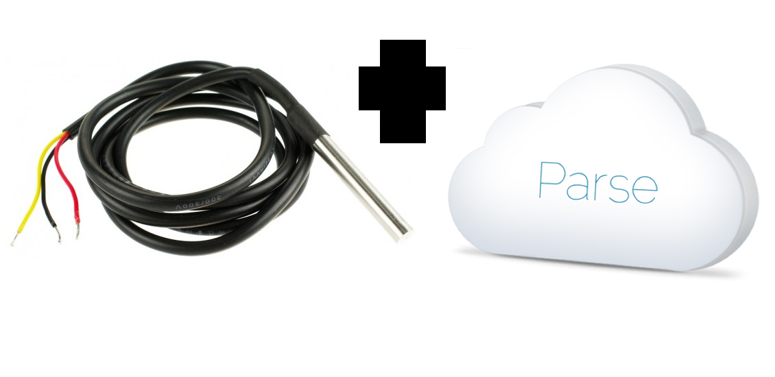
Raspberry Pi, Parse.com, and Temperature Logging


As part of a future project I may be working on(details coming soon). I wanted to get some logging done with some temperature sensors to the online cloud database called Parse.com
If you want your data stored on the cloud to be able to access anywhere this is what you will need to do:
  • install the DS18b20 temperature probes

Parse App Setup

 copy the application id and the rest api key to your python script

Get the ParsePy library:

install on your pi using the command

git clone https://github.com/dgrtwo/ParsePy
cd ParsePy
sudo python setup.py install

Getting my Logging Library:

download here:
https://github.com/SimplyAutomationized/raspberrypi/raw/master/ParseTempLogging/ParseTemperature.py
usage:
from ParseTemperature import *
logger = TempLogger(appkey='yourappkey',apikey='yourapikey')
logger.start()#will create the class in your app and start appending temperature data to it whenever the temperature changes. 

Now the two sensors started populating my online db. 

for reference here's the logging libarary:

from parse_rest.connection import register
from parse_rest.datatypes import Object

from threading import Thread
from time import sleep
import os
os.system('modprobe w1-gpio')
os.system('modprobe w1-therm')
class Temperature(Object):
 pass


class TempLogger(Thread):
 """
 A class for getting the current temp of a DS18B20
 """
 def __init__(self, fileName='',debug=False,appkey='',apikey=''):
  Thread.__init__(self)
  register(appkey,apikey)#put your api key and app id here
  self.debug = debug
  self.probes = {}
  self.tempDir = '/sys/bus/w1/devices/'
  self.currentTemp = -999
  self.correctionFactor = 1;
  self.enabled = True
  self.repopulateprobes()
 def repopulateprobes(self):
  list = os.listdir(self.tempDir)#here we create a dictionary with the probe id's
  for item in list:
   if(item[:2]=="28"):
   if(self.debug):
    print item
   if(self.probes.has_key(item)==False):
    self.probes[item]=0

 def getTempForFile(self,file):
  try:
   f = open(self.tempDir + file + "/w1_slave", 'r')
  except IOError as e:
   print "Error: File " + self.tempDir + file + "/w1_slave" + " doesn't exist"
   return;
  lines=f.readlines()
  crcLine=lines[0]
  tempLine=lines[1]
  result_list = tempLine.split("=")
  temp = float(result_list[-1])/1000 # temp in Celcius
  temp = temp + self.correctionFactor # correction factor
  #if you want to convert to Celcius, comment this line
  temp = (9.0/5.0)*temp + 32
  if crcLine.find("NO") > -1:
   temp = -999
  if(self.debug):
   print "Current: " + str(temp) + " " + str(file)
  return float(int(temp*100))/100    
 def run(self):
  while self.enabled:
   for item in self.probes.items(): #we iterate through our probes we scanned for earlier and save temperatures to the dictionary
    temp = self.getTempForFile(item[0])
    if(item[1]!=temp):#if there is a change in the temperature we send it to parse
     parseDBObject=Temperature()
     parseDBObject.Probe=item[0]
     parseDBObject.Temperature=temp
     try:
      parseDBObject.save()
     except:
      pass
     self.probes[item[0]]=temp
 def stop(self):
  self.enabled=False
    #returns the current temp for the probe
 def getCurrentTemp(self,file):
  return self.probes[file]

Sunday, August 10, 2014

A Simple Interface for the Internet of Things with my Raspberry Pi

A Simple Interface for the Internet of Things

Awhile back I bought the Adafruit starter kit for the LPC810.
LPC811  on a TSSOP-16 breakout board

With much trial and error I was able to get a simple serial communication with it through a ttl usb cable.  I then wanted to control the I/O remotely. This device can be polled for status and controlled through tcp messages from your Android/iOS device and Raspberry Pi

My Remote Control portable plug
Parts:

  • 1 - LPC810
  • 1 - HLK-RM04
  • 1 - ULN2803APG
  • 3 - 1k ohm Resistors
  • 1 - 120v to 5v 500mA converter module (ebay)
  • 1 - 2Ch relay module
  • 1 - prototyping board

and connected it all up:


simple code for controlling my plugs in python:

import socket
class PlugPoller(threading.Thread):
 def __init__(self,ip,port):
  threading.Thread.__init__(self)
  self.ip=ip
  self.port=port
  self.connect(ip,port)
  self.status='0000'
  self.command='!getstat\r'
 def connect(self,ip,port):
  try:
   self.s=socket.socket(socket.AF_INET,socket.SOCK_STREAM)
   self.s.settimeout(1)
   self.s.connect((ip,port))
  except:
   pass
 def run(self):
  while True:
   try:
    sleep(.1)
    self.s.send(self.command)
    self.status=str(self.s.recv(4))
    #print "data:{"+self.command,self.status+"}"
   except:
    print 'error'
    sleep(5.0)
    self.connect(self.ip,self.port)
    pass
   if(self.command!='!getstat\r'):
    #print self.command
    self.command='!getstat\r'
 def getstatus(self):
  return self.status
 def sendcmd(self,c):
  try:
   self.s.send(c)
  except:
   pass
  return self.s.recv(4)
def main():
 plug=PlugPoller("192.168.16.254",8080)
 plug.start()#start the async status poller
 plug.sendcmd('!turnon1') #turns on relay 1
 plug.sendcmd('!trnoff1') #turns off relay 1
 plug.getstatus() #returns a status of 0001, first two binary numbers are the button inputs the last two are the relays
 plug.sendcmd('!talloff')#turns off all relays
Whenever these inputs are pressed it will toggle the relays locally. The pushbuttons  would be connected to the right side of the Wifi Module.   Giving you remote and local control of your device without having to put an Arduino or Raspberry Pi in that enclosure.
For me I like knowing instantly whether my light is on while looking at it remotely. The PlugPoller python script is polling statuses every tenth of a second.  The MCU and the module talk at 115k baud so you can get your results pretty quickly.

Since that looked pretty ugly (prototype), i'm currently working with the LPC811 which has more I/O.  14 configurable pins, 2 of which I will use for UART communication (12 for I/O pins) which will let you sense more inputs and turn on more outputs.  These chips can have some of these pins configured for i2c and spi that can connect you to 100s of sensors that you can have through wifi.


Please Comment if you wish to see this as a kit you could buy
Or if you have questions

Monday, July 7, 2014

Raspberry Pi SCADA Part 2, Modbus TCP PWM Controller

Raspberr Pi SCADA Part 2, Modbus PWM Controller

Since finding a cheap alternative to PLC whilst using an industrial protocol is a popular idea the Raspberry Pi has caught many eyes on doing this.  I posted once on reading a temperature sensor and serving it up on the Pi using ModbusTCP. This time I expound on it and show you how to control something. In this case it will be a PC 12v fan.

Parts:

  • 1 x Raspberry pi
  • 1 x Darlington Transistor
  • 1 x PC Fan (with about  500ma load)
  • 1 x 12v DC Power Supply


Setup:

  1. Installing pymodbus and dependencies:
    • sudo apt-get install python-pymodbus python-twisted-conch
  2. Wire up your Fan, LED, or motor


  1. View my code from Github.
Video of what I did:


Source Code:
from pymodbus.server.async import StartTcpServer
from pymodbus.device import ModbusDeviceIdentification
from pymodbus.datastore import ModbusSequentialDataBlock, ModbusSlaveContext, ModbusServerContext
from pymodbus.transaction import ModbusRtuFramer, ModbusAsciiFramer
from twisted.internet.task import LoopingCall
from threading import Thread
import pid
import threading
from time import sleep
import RPi.GPIO as GPIO
import os
os.system('modprobe w1-gpio')
os.system('modprobe w1-therm')
#set up Raspberry GPIO 
GPIO.setmode(GPIO.BCM)
GPIO.setwarnings(False)
GPIO.setup(25,GPIO.OUT)
pwm = GPIO.PWM(25,60)
pwmDutyCycle=100
pwm.start(pwmDutyCycle)
temperaturePoll = None

class Temp(Thread):
    """
     A class for getting the current temp of a DS18B20
    """
    def __init__(self, fileName=''):
        Thread.__init__(self)
        super(Temp, self).__init__()
        self._stop = threading.Event()
        self.tempDir = '/sys/bus/w1/devices/'
        list = os.listdir(self.tempDir)
        if(list[0][:2]=="28"):
         fileName=list[0]
        self.fileName = fileName
        self.currentTemp = -999
        self.correctionFactor = 1;
        self.enabled = True
        self.Run=True
    def run(self):
        while self.isEnabled():
   try:
    f = open(self.tempDir + self.fileName + "/w1_slave", 'r')
   except IOError as e:
    print "Error: File " + self.tempDir + self.fileName + "/w1_slave" + " does not exits"
    return;
   lines=f.readlines()
   crcLine=lines[0]
   tempLine=lines[1]
   result_list = tempLine.split("=")
   temp = float(result_list[-1])/1000 # temp in Celcius
   temp = temp + self.correctionFactor # correction factor
   #if you want to convert to Celcius, comment this line
   temp = (9.0/5.0)*temp + 32
   if crcLine.find("NO") > -1:
    temp = -999
   self.currentTemp = temp
   #print "Current: " + str(self.currentTemp) + " " + str(self.fileName)
   sleep(.5)
    #returns the current temp for the probe
    def getCurrentTemp(self):
        return self.currentTemp
    #setter to enable this probe
    def setEnabled(self, enabled):
        self.enabled = enabled
    #getter
    def isEnabled(self):
        return self.enabled


def updating_writer(a):
 context  = a[0]
 register = 3
 slave_id = 0x00
 address  = 0x00
 global pwmDutyCycle,temp
 #uncomment to debug temperature
 print temp.getCurrentTemp()
 values = [int(pwmDutyCycle),temp.getCurrentTemp()*100]
 context[slave_id].setValues(register,address,values)
def read_context(a):
 context  = a[0]
 register = 3
 slave_id = 0x00
 address  = 0x00
 value = context[slave_id].getValues(register,address)[0]
 global pwmDutyCycle
 if(value!=pwmDutyCycle):
  print value
  pwmDutyCycle=value
  pwm.ChangeDutyCycle(pwmDutyCycle)
def main():

 store = ModbusSlaveContext(
  di = ModbusSequentialDataBlock(0, [0]*100),
  co = ModbusSequentialDataBlock(0, [0]*100),
  hr = ModbusSequentialDataBlock(0, [0]*100),
  ir = ModbusSequentialDataBlock(0, [0]*100))
 context = ModbusServerContext(slaves=store, single=True)
 identity = ModbusDeviceIdentification()
 identity.VendorName  = 'pymodbus'
 identity.ProductCode = 'PM'
 identity.VendorUrl   = 'http://github.com/simplyautomationized'
 identity.ProductName = 'pymodbus Server'
 identity.ModelName   = 'pymodbus Server'
 identity.MajorMinorRevision = '1.0'
 time = 5 # 5 seconds delaytime = 5 # 5 seconds delay
 writer = LoopingCall(read_context,a=(context,))
 loop = LoopingCall(updating_writer, a=(context,))
 loop.start(.5) # initially delay by time
 writer.start(.1)
 StartTcpServer(context, identity=identity)#, address=("localhost", 502))
 #cleanup async tasks
 temp.setEnabled(False)
 loop.stop()
 writer.stop()
 GPIO.cleanup()
if __name__ == "__main__":
 temp = Temp()
 temp.start()
 main()

Monday, February 24, 2014

Home Automation Project #4 1-Wire I/O Performance Test

Dallas has a couple 1-Wire I/O chips out there.  I decided to test the one that seemed practical to replace a light switch or plug. The DS2413 was almost perfect.  It has 2 I/O, gets power from the data line, and Adafruit made it easy for me to test by making the breakout board.

Here's what I used for my test:


With these I created a demo to see the read and write speeds through the 1-wire data line.
Source code for benchmark:

As you can see the performance dropped more than half every time I pressed the button.  Not bad if all I care about is whether the light turns on right when I press the button, and it would.
I then ran the loop to see how fast it would go at turning on and off the relay and saw an average of 20.833 requests per second. (Don't worry, the relay wasn't able to click on and off that fast)

Adding a DS18B20 Temperature sensor and requesting it every second I found that when the temperature was requested the requests per second dropped down to 1.950 requests per second and then jumped back up to the 42.27 range until the next second came along.

Requesting the temperature every loop cycle was unworkable.  I had to hold my finger on the button far longer than desired to get the relay to turn on.  I tuned it up by requesting the lesser accurate temperature value "fasttemp".  I also requested it less often (every other second).

t=ow.Sensor('/28.B0A534050000')
t.useCache(False)
print t.fasttemp

The DS2413 datasheet mentions the ability for Overdrive (~10x the communication speed) but I was unsuccessful on getting it to work.  The communication would seize when I tried enabling it on the bus.

Conclusion:
Controlling your lights with the DS2413 is possible, but you are limited on the quantity of chips on the same bus line. If you are able to get the chip's Overdrive feature working then I would suggest getting the 8-port i2c to 1-wire add-on board if you have plans for your whole house.

I'm going to test the DS2408 (8 port 1-Wire I/O chip) soon and am a little more hopeful since you can control multiple rooms and/or lights with one chip.

(Pictures coming soon.)